Awesome
CAN_OMEGA
Ultimate CAN Bus tool for Car hacking.
Command set is compatible with USBTin
Features
Support full OBD-II Features including followings:
ISO15765 CAN250Kbps 11bit
ISO15765 CAN250Kbps 29bit
ISO15765 CAN500Kbps 11bit
ISO15765 CAN500Kbps 29bit
ISO9141-2 5bps Init
ISO14230 KWP2000 5bps Init
ISO14230 KWP2000 Fast Init
SAE J1850 PWM
SAE J1850 VPW
Multi-Frame Support
Soft-controlled end-point matching resistors.
Support for incomming CAN FD. (use MCP2517FD in place of MCP2515)
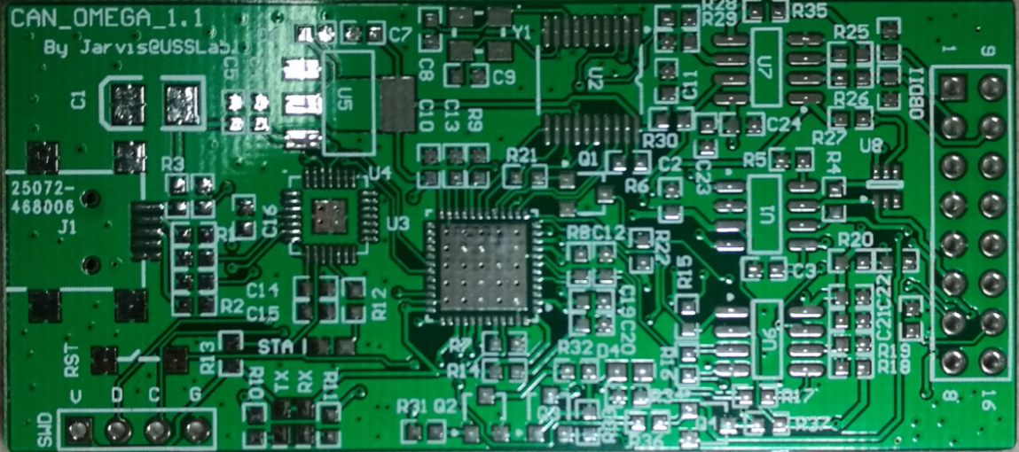
v1.1 PCB Photo
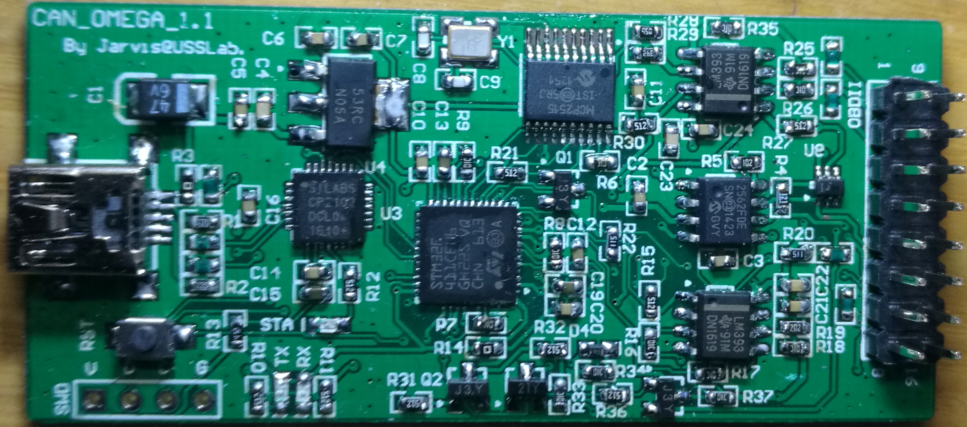
v1.1 Assembled Board
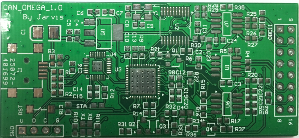
v1.0 PCB Photo
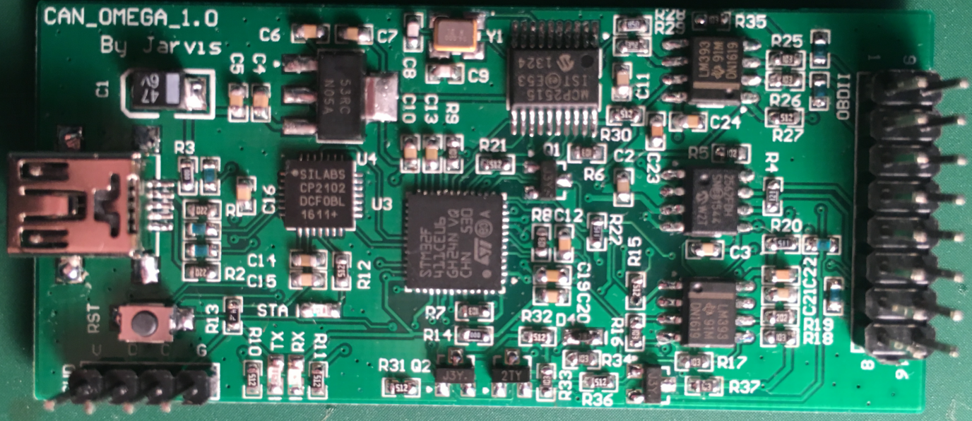
v1.0 Assembled Board
Drivers
CAN Omega use CP2102 chip to convert UART to USB.
For Linux, Windows >8 no additional driver is needed!
CAN Omega will be automatically detected as virtual serial port.
Device is mapped to serial port "/dev/ttyUSBx" (Linux) or "COMx" (Windows).
For Windows<8 and Mac OS, you can get the corresponding drivers here:
http://www.silabs.com/products/mcu/pages/usbtouartbridgevcpdrivers.aspx
And On MacOS the Device's serial Port will become "/dev/tty.SLAB_USBtoUART", you needed input the port name manually.
The Serial Port works in 115200 8 N 1 Mode.
Firmware Repository
See here for more details: https://github.com/zjlywjh001/CAN_Omega_Firmware
Notice: Firmware should work with the bootloader, but the source code of the bootloader can't be released due to some license issues. So I can only release the bootloader in binary.
A cross platform GUI tool.
See here for more details: https://github.com/zjlywjh001/CAN_OMEGA_Tools
Requirement: JRE >= 1.8

This tool offers the following functions:
CAN/K-Line/J1850 Packet Transreceiver
CAN Packet Analysis
CAN Fuzzing tool
Frimware Update
Command Set
Following commands are inherited from USBTin's Command Set:
Sx[CR]:--------Set CAN Bus baudrate
x: Bitrate id (0-8)
S0 = 10 kBaud
S1 = 20 kBaud
S2 = 50 kBaud
S3 = 100 kBaud
S4 = 125 kBaud
S5 = 250 kBaud
S6 = 500 kBaud
S7 = 800 kBaud
S8 = 1 MBaud
sxxyyzz[CR]--- -Set can bitrate registers of MCP2515. You can set non-standard baudrates which are not supported by the "Sx" command.
xx: CNF1 as hexadecimal value (00-FF)
yy: CNF2 as hexadecimal value (00-FF)
zz: CNF3 as hexadecimal value
Gxx[CR] --- Read MCP2515 register.
xx: Address of MCP2515 register to read as hexadecimal value (00-FF).
Wxxyy[CR] ---Write MCP2515 register.
xx: Address of MCP2515 register to write. Hexadecimal value (00-FF).
yy: Data to write to the register. Hexadecimal value (00-FF).
V[CR]---Get hardware version
v[CR]---Get firmware version.
N[CR]---Get serial number. Returns always 0xffff.
O[CR]---Open CAN channel.
l[CR]---Open device in loop back mode.
L[CR]---Open CAN channel in listen-only mode.
C[CR]---Close CAN channel
tiiildd..[CR]---Transmit standard (11 bit) frame.
iii: Identifier in hexadecimal format (000-7FF)
l: Data length (0-8)
dd: Data byte value in hexadecimal format (00-FF)
Tiiiiiiiildd..[CR]---Transmit extended (29 bit) frame.
iiiiiiii: Identifier in hexadecimal format (0000000-1FFFFFFF)
l: Data length (0-8)
dd: Data byte value in hexadecimal format (00-FF)
riiil[CR] --- Transmit standard RTR (11 bit) frame.
iii: Identifier in hexadecimal format (000-7FF)
l: Data length (0-8)
Riiiiiiiil[CR]---Transmit extended RTR (29 bit) frame.
iiiiiiii: Identifier in hexadecimal format (0000000-1FFFFFFF)
l: Data length (0-8)
F[CR]---Read status/error flag of can controller
Return: Fxx[CR] with xx as hexadecimal byte with following error flags:
Bit 0 - not used
Bit 1 - not used
Bit 2 - Error warning (Bit EWARN of MCP2515)
Bit 3 - Data overrun (Bit RX1OVR or RX0OVR of MCP2515)
Bit 4 - not used
Bit 5 - Error-Passive (Bit TXEP or RXEP of MCP2515)
Bit 6 - not used
Bit 7 - Bus error (Bit TXBO of MCP2515)
Zx[CR]---Set timestamping on/off.
x: 0=off, 1=on
mxxxxxxxx[CR]---Set accpetance filter mask. SJA1000 format (AM0..AM3). Only first 11bit are relevant.
xxxxxxxx: Acceptance filter mask
Mxxxxxxxx[CR]---Set accpetance filter code. SJA1000 format (AC0..AC3). Only first 11bit are relevant.
xxxxxxxx: Acceptance filter code
And the following commands are added in CAN Omega:
b[CR] --- reset Device
f -- CAN Fuzzing Function
Examples:
fz[CR] --- Pause Fuzzing
fP[CR] --- Stop Fuzzing
fr[CR] --- Resume Fuzzing
fuzzing config format:
f [d/D] [id] [dlc] [s/S] [FROM] [TO] [g/G] p [period] (u [until] m [mask]) [CR], part in bracket is depend on [s/S] option
[d/D] means extended frame or not. d represent for fuzzing 11bit packet,[id] should be 11 bit, 'D' means 29bit
[dlc] is packet len
[s/S] 's' means this config has a until config, when a receiving packet match the pattern the fuzzing will stop. And 'S' for fuzzing without a 'until' config.(with out the data in brackets)
[FROM] is the start packet, encoded in hex
[TO] is the end packet, encoded in hex
(Every byte in [TO] config should be strict greater than correspoding byte in [FROM])
[g/G] is the fuzzing order. g for left byte first increase, and G for right byte first increase
[period] the time delay between two packets, unit in microsecond(us), encoded in hex.
[until] [mask] until is a packet of length 8,and mask decide which byte in [until] shoud be math, 1 - match 0 - not care
the bit 0 of mask is for the far left byte, and bit 7 is the far right byte
example1:
fd0013s0201000201FFgp3E8u0201050000000000m05
fuzzing id:001
dlc: 3
fuzzing from 02 01 00
fuzzing to 02 01 FF
left byte increase first
period 1ms
until on receive 02 01 05-- only compare 02 and 05
example2:
fD000007DF3S0201000201FFGp3E8
fuzzing id:000007DF
dlc: 3
fuzzing from 02 01 00
fuzzing to 02 01 FF
left byte increase first
period 1ms
no until settings
k -- K line transrece function
kak[CR] --- Activate ECU in KWP2000 Fast Init Mode
kai[CR] --- Activate ECU in ISO9141-2 5BPS Init Mode
kaI[CR] --- Activate ECU in KWP2000 5BPS Init Mode
the last two mode is a bit slow, may take 5-15 seconds to activate ECU, when activated successfully, will return o[CR] bytes.
So be patient when using these protocols.
kk [len] [data] [CR] --- Send K Line Message after activated
the return data format is kXXXXXXXXXXXX[CR] encoded in hex
d[CR] --- deactive K Line
jp [len] [Data] [CR] -- Send J1850 Packet in PWM Mode
jv [len] [Data] [CR] -- Send J1850 Packet in VPW Mode
U[CR] --- Reboot and enter bootloader
Notice:
When Entering Bootloader it will wait for 3 seconds for another 'U' char. When Received 'U' with in 3 seconds, the bootloader will start firmware update function.
Following Commands are available in CAN Omega 1.1 or later hardware only.
A[CR] --- Set Terminal Resistor to Open Circuit (Default on boot)
a[CR] --- Set Terminal Resistor to 120-Ohms
License
MIT License