Awesome
Chorus-RF-Laptimer-PCB
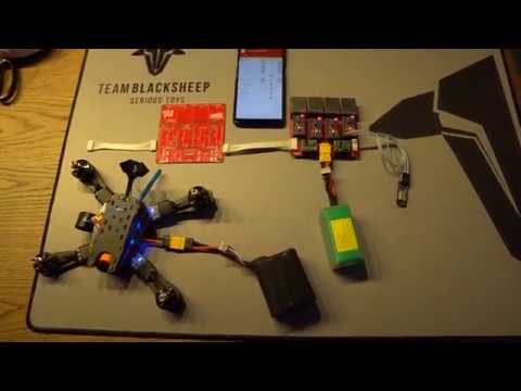
4in1 PCB for the Chorus RF Laptimer by Andrey Voroshkov https://github.com/voroshkov/Chorus-RF-Laptimer
<img src="https://raw.githubusercontent.com/ps915/Chorus-RF-Laptimer-PCB/master/p3.JPG" width="350"> <img src="https://raw.githubusercontent.com/ps915/Chorus-RF-Laptimer-PCB/master/p1.JPG" width="350">
https://www.youtube.com/watch?v=avLRJ5z0UP4
Features
- PCB for 4 Nodes (4 Pilots)
- easy extendable via JST XH cable (8 Pilots)
- 5V stepdown for Arduinos
- adjustable stepdown for RX Modules (use 3.5V to keep temperature low)
- 92 x 92mm mounting holes
- XT60 PowerIn
- 5V USB PowerIn (if you want to use a powerbank)
- stacked hardware - can be changed in seconds
- Buzzer Port to connect one Buzzer per Node
Changelog
ALL RELEASES
22.05.2018 - v3.1 beta released DOWNLOAD
- inital release
- i did not tested this PCB. To V3.0 i just added the Diodes and did cleaned it up a bit. V3.0 worked so far. Please report any issues!
Important
Less than 4 nodes?
You can use less than 4 nodes. All you have to do, is to bridge TX/RX (see silkscreen) of the unused nodes. Always use at least "Node1" because the voltage measurement is connected to this node.
5 V power via USB
If you want to power the unit via 5 V USB, please remove stepdown marked as "Arduino" and bridge IN and OUT of it to pass the power from the USB to the Arduios.
How to track 8 pilots and more
If you plan to track more than 4 pilots at the same time, connect just connect two or more PCBs together.
- Please always set the Loopback Jumper to the first PCB.
- Connect the next PCB via 6Pin JST cable
- On the first PCB, bridge MV
- On following PCBs please bridge GM
- WiFi/Bluetooth Module always connects to the last PCB. <img src="https://raw.githubusercontent.com/ps915/Chorus-RF-Laptimer-PCB/master/p5.jpg">
What do you need (4 nodes)
- 1x 4in1 PCB
- 4x Arduino Pro Mini
- 4x RX5808 (with SPI mod)
- 12x 100 ohm 1206 SMD Resistor
- 4x 1k ohm 1206 SMD Resistor
- 1x 10k 1% ohm 1206 SMD Resistor
- 1x 1k 1% ohm 1206 SMD Resistor
- 4x 1n5817 smd 1A 20V do-214ac Schottky diode
- 2x 6 Pin JST XH 90° Connector
- 1x USB Breakout Board
- 2x Pin Jumper
- 1x DT-06 WiFi Module
- 1x 5V Stepdown
- 1x adjustable stepdown
- optional 6Pin JST XH cable for connecting two or more PCBs together
- 1x XT60
- 4x 3Pin Pin Header Socket
- 4x 6Pin Pin Header Socket
- 4x 12Pin Pin Header Socket
- 16x 2Pin Pin Header Socket
- manny Pin Header RM 2.54
(some links are affiliate links)
Software
https://github.com/voroshkov/Chorus-RF-Laptimer
Blog post about the project
- english https://blog.seidel-philipp.de/chorus-rf-laptimer-4in1-pcb-english/
- deutsch https://blog.seidel-philipp.de/chorus-rf-laptimer-4in1-pcb/
Ordering the PCB
you can order the PCB from china:
- Go to FUSION PCB www.seeedstudio.com
- Upload gerber file (chorus_4in1_3.1_gerber_file.zip)
- verify order settings
- Base Material: FR-4
- No. of Layers: 2
- PCB Dimensions: 100mm x 100mm
- PCB Quantity: 10 (you will get 10 identical PCBs - thats the minimum quantity)
- No. of Different Designs: 1
- PCB Thickness: 1.6mm
- PCB Color: Red
- Surface Finish: HASL
- Minimum Solder Mask Dam: 0.4mm
- Copper Weight: 1oz
- Minimum Drill Hole Size: 0.3mm
- Trace Width / Spacing: 6/6 mil
- Blind or Buried Vias: No
- Plated Half-holes / Castellated Holes: No
- Impedance Control: No
- add to cart
- pay the order! Done!
- share unused PCBs with the community! =)