Awesome
MiniVGA
MiniVGA generates a 200x150 @ 60Hz 3-bit color VGA signal. The interface is simple and can be controlled by GPIO from any number of devices, such as Arduino microcontroller dev boards or custom built retrocomputers.
Having recently built the Vectron VGA VGA generator from 7400-series logic chips, I decided to build an FPGA-based device to provide video output for my Vectron 64 breadboard computer that would not take up half of my desk.
How It Works
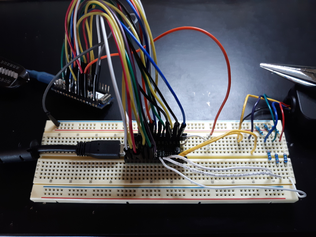
A TinyFPGA BX has been programmed to generate an 800x600 @ 60Hz VGA signal. Each pixel is repeated 4 times horizontally and vertically to yield a resolution of 200x150 pixels. Screen data is continually refreshed based on the data stored in a section of the BRAM dedicated to this purpose.
The interface consists of a 15 bit address bus, 3 bit data bus, and an interrupt signal. To set a pixel color, set the desired address on the address bus (top left pixel = 0; bottom right pixel = 29,999).
<p align="center"> <img src="https://raw.githubusercontent.com/nickbild/fpga_vga/master/media/pixel_numbering3.png"> </p>Next, set the color value on the data bus:
| bit 2 | bit 1 | bit 0 |
|---|---|---|
| Blue | Green | Red |
A 1 is full on, and 0 is full off. A total of 8 colors can be generated. With address and data choices set, send a high pulse to the interrupt. This writes the pixel data to BRAM and the VGA generator will display it on the next frame (60 frames / second).
Voltage dividing resistors are required on the RGB lines to bring the voltage down to 0.7V. 357 ohms from the TinyFPGA signals, and 100 ohms to ground.
To demonstrate the functionality, I have written some example Arduino code available here. I also have an example for interfacing from a Raspberry Pi 3 B+.
Media
MiniVGA being driven by an Arduino Nano 33 IoT:

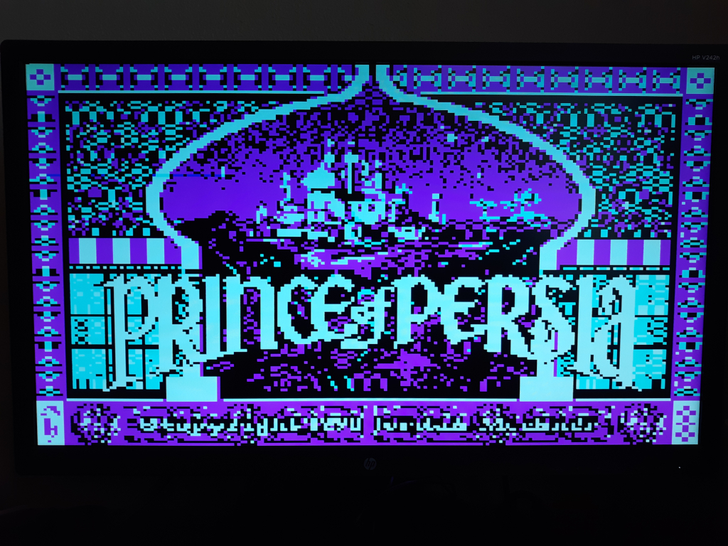
Prince of Persia title screen:

Bill of Materials
- 1 x TinyFPGA BX
- 1 x Arduino Nano 33 IoT
- 1 x VGA breakout board
- Miscellaneous wires