Awesome
Raspberry PI Lora Gateway/Node for RFM92/95/96/98/69HCW Modules
<img src="https://raw.githubusercontent.com/hallard/RPI-Lora-Gateway/master/images/RPI-Lora-Gateway-mounted.jpg" height="40%" width="40%" alt="Raspberry PI Lora Gateway/Node">This shield is used to hold one or two HopeRF Lora module Software with Raspbery PI plus one FM12B/RFM69CW/RFM69(H)W. it's the parent of the small LoRasPi, so please look at LoRasPi readme to see features and software links.
This board has been mainly inspired from Uptronics expansion board on which I added some features but it's not a real LoraWAN concentrator, if you need a real concentrator with multiple channels and fully compliant to LoraWan stack capabilities, please see thethingsnetwork wiki dedicated to gateways.
By the way, with Lora modules installed on this board you can have it working as a Single Channel Gateway or a LoraWan node. For testing, demo or small projects, it can be enought.
Quick features
- Placement for two RFM92/95/96/98 Lora module (IE one 868MHz and one 433MHz, or 2 channels 868MHz)
- Placement for one RFM12B/RFM69CW/RFM69(H)W classic module
- Placement for choosing single Wire, SMA, u-FL or Thru Hole PCB Mount (Right Angle Tor straight) by Eightwood Antenna type
- Vertical Antenna placement is possible (easier to drill RPI top enclosure)
- 4 x LED for visual indication
- Each Module reset pin can be connected to a RPI GPIO
Boards arrived from ElectroDragon, all is working as expected.
Detailed Description
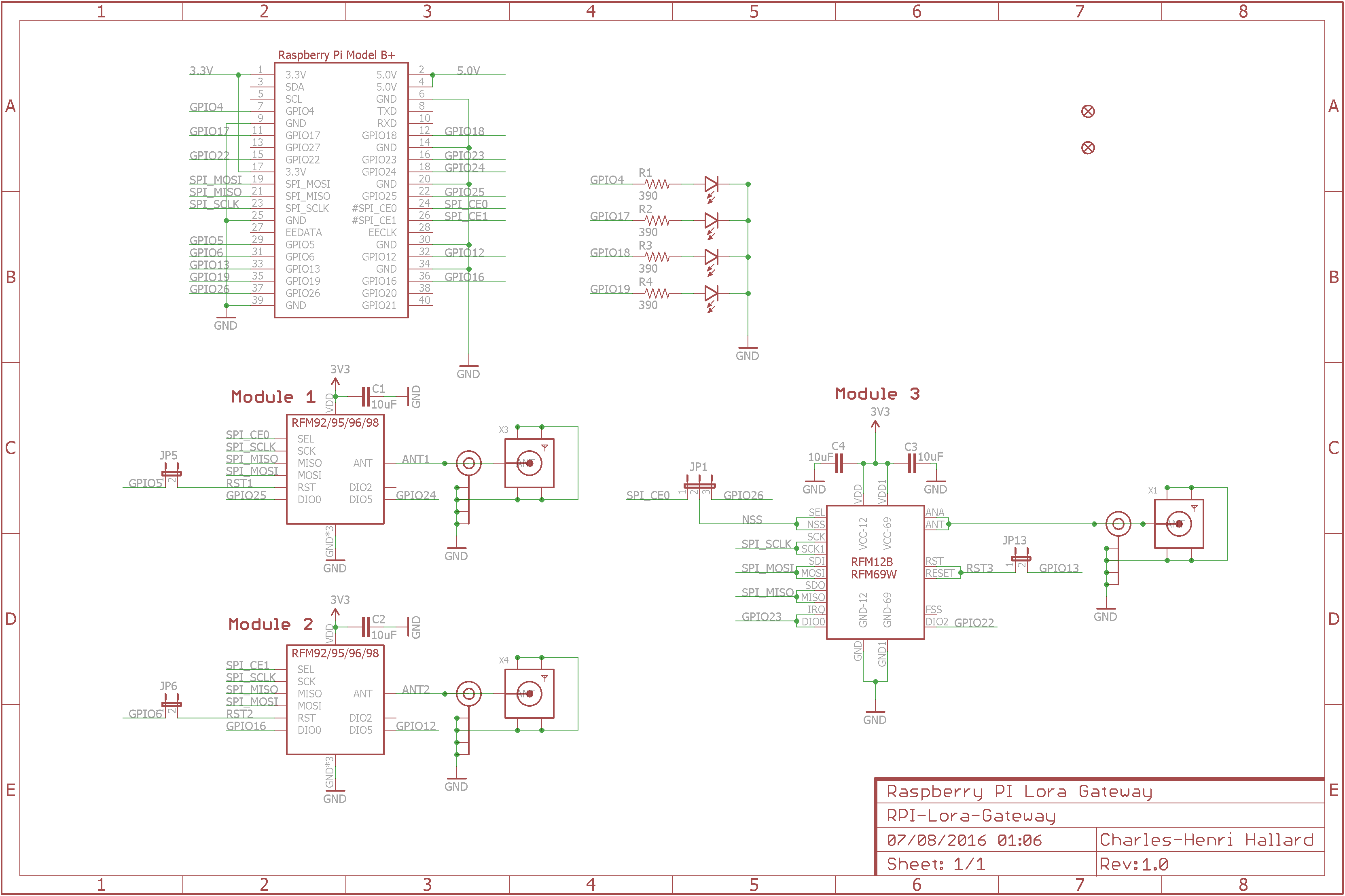
Look at the schematics for more informations.
SPI connexion is classic (MOSI/MISO/CLK), Chip Select is CE0 for Module 1 and CE1 for Module 2. Module 3 can be choosen between CE0 and GPIO26 with on board jumper switch.
Raspberry PI   RFM9x Module 1
   CE0     <---->  SEL
   GPIO5   <---->  Reset (JP5)
   GPIO25  <---->  DIO0
   GPIO24  <---->  DIO5

Raspberry PI   RFM9x Module 2
   CE1     <---->  SEL
   GPIO6   <---->  Reset (JP6)
   GPIO16  <---->  DIO0
   GPIO12  <---->  DIO5

Raspberry PI   RFM69/12 Module 3
 IO26/CE0  <---->  SEL
  GPIO13   <---->  Reset (JP13)
  GPIO23   <---->  DIO0
  GPIO12   <---->  DIO2

Raspberry PI   On Board LEDS
   GPIO4   <---->  LED 4
   GPIO17  <---->  LED 17
   GPIO18  <---->  LED 18
   GPIO19  <---->  LED 19
Hardware Setup
Nothing really complicated, you can wire Reset of each module on a GPIO pin if you want to be able to hardware reset then using software, in this case put jumper on JP5 for Module 1, JP6 for Module 2 and JP13 for Module 3. JPx number is the GPIO so JP5 is for GPIO5 ;-)
If you want to use Module 1 and Module 3 you need to set JP1 (Chip Select of module 3) to IO26 since CE0 is used by Module 1.
Software Setup
I'm working on two libraries port and Single Channel Gateway to work on Raspberry PI, links are here
- LMIC to be LoraWan compliant. This LMIC is working with this shield, see readme of repo.
- Excellent RadioHead twekaed library for RFM69, RFM9x modules (and lot of others). This version is working with this shield, see readme of library.
- The Things Network Single Channel Gateway packet forwarder
I forked all repos to tweak them, but since I'm not sure original authors would like to merge my changes just use my forks.
For reference, original libraries and code are Arduino-LIMC, RadioHead-LIMC, Single Channel Gateway packet forwarder
Schematic
Boards
<img src="https://raw.githubusercontent.com/hallard/RPI-Lora-Gateway/master/images/RPI-Lora-Gateway-top.png" alt="Top" height="45%" width="45%" > <img src="https://raw.githubusercontent.com/hallard/RPI-Lora-Gateway/master/images/RPI-Lora-Gateway-bot.png" alt="Bottom" height="45%" width="45%">
Received boards
<img src="https://raw.githubusercontent.com/hallard/RPI-Lora-Gateway/master/images/RPI-Lora-Gateway-top.jpg" height="45%" width="45%" alt="Top"> <img src="https://raw.githubusercontent.com/hallard/RPI-Lora-Gateway/master/images/RPI-Lora-Gateway-bot.jpg" height="45%" width="45%" alt="Bottom">
You can order the PCB of this board PCBs.io. PCBs.io give me some reward when you order my designed boards from their site. This is pretty good, because I can use these rewards to create and design new boards and order boards for a discounted price and share new boards.
Assembled and mounted board
Here is my testing board, as you can see, 3 modules on it
- Module 1 (top left) Lora RFM95 868MHz
- Module 2 (bottom left) Lora RFM98 433MHz
- Module 3 (right) RFM69HW 433MHz
##License
You can do whatever you like with this design.
##Misc See news and other projects on my blog