Awesome
UnityTerrainErosionGPU
Hydraulic and thermal erosion implement in Unity using compute shaders.
This is an example implementation of hydraulic and thermal erosion with shallow water equations. My initial motivation was to implement a game mechanic like in the From Dust game.
Disclaimer
This project is still in progress. Hydraulic erosion requires a bit more parameter tweaking and revisiting the actual implementation. But overall it works.
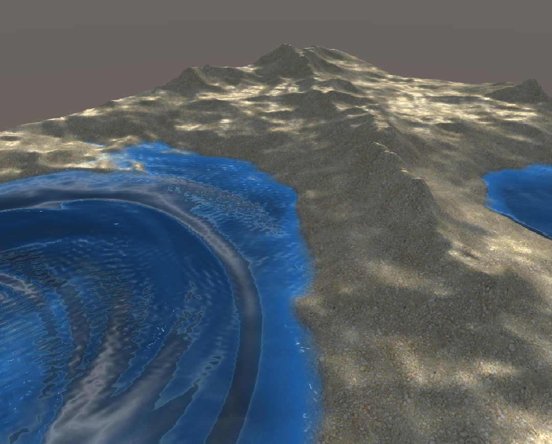
Demo
Just run Main Scene and use the mouse to draw modify terrain/water.
How it works
Explanation is still in progress...
Data / notation
We first need to list all the data we will operate with during the simulation. Since we are using a grid-based simulation we will need some per-cell information. Assuming we have a grid of size <img src="https://tex.s2cms.ru/svg/W%20%5Ctimes%20H" alt="W \times H" /> and current cell coordinates are <img src="https://tex.s2cms.ru/svg/(i%2C%20j)" alt="(i, j)" />.
- Simulation parameters
- <img src="https://tex.s2cms.ru/svg/W" alt="W" /> - grid width
- <img src="https://tex.s2cms.ru/svg/H" alt="H" /> - grid height
- <img src="https://tex.s2cms.ru/svg/%5CDelta%20t" alt="\Delta t" /> - simulation time delta
- <img src="https://tex.s2cms.ru/svg/g" alt="g" /> - gravity
- <img src="https://tex.s2cms.ru/svg/l_x" alt="l_x" /> - cell size along <img src="https://tex.s2cms.ru/svg/x" alt="x" /> axis
- <img src="https://tex.s2cms.ru/svg/l_y" alt="l_y" /> - cell size along <img src="https://tex.s2cms.ru/svg/y" alt="y" /> axis
- <img src="https://tex.s2cms.ru/svg/l" alt="l" /> - pipe length
- <img src="https://tex.s2cms.ru/svg/A" alt="A" /> - pip cross-section area
- <img src="https://tex.s2cms.ru/svg/K_e" alt="K_e" /> - evaporation rate
- <img src="https://tex.s2cms.ru/svg/K_r" alt="K_r" /> - rain rate
- Hydraulic erosion parameters
- <img src="https://tex.s2cms.ru/svg/K_c" alt="K_c" /> - sediment capacity
- <img src="https://tex.s2cms.ru/svg/K_s" alt="K_s" /> - soil suspension rate
- <img src="https://tex.s2cms.ru/svg/K_d" alt="K_d" /> - soil deposition rate
- <img src="https://tex.s2cms.ru/svg/l_%7Bmax%7D" alt="l_{max}" /> - erosion depth limit
- Thermal erosion parameters
- <img src="https://tex.s2cms.ru/svg/K_t" alt="K_t" /> - thermal erosion rate
- <img src="https://tex.s2cms.ru/svg/K%5Es_%5Calpha" alt="K^s_\alpha" /> - talus angle scale
- <img src="https://tex.s2cms.ru/svg/K%5Eb_%5Calpha" alt="K^b_\alpha" /> - talus angle bias
- Grid-values
- <img src="https://tex.s2cms.ru/svg/h%5E%7Bterrain%7D_%7Bi%2Cj%7D" alt="h^{terrain}_{i,j}" /> - height of terrain in cell <img src="https://tex.s2cms.ru/svg/(i%2C%20j)" alt="(i, j)" />, must be positive
- <img src="https://tex.s2cms.ru/svg/h%5E%7Bwater%7D_%7Bi%2Cj%7D" alt="h^{water}_{i,j}" /> - height of water in cell <img src="https://tex.s2cms.ru/svg/(i%2C%20j)" alt="(i, j)" />, must be positive
- <img src="https://tex.s2cms.ru/svg/s_%7Bi%2Cj%7D" alt="s_{i,j}" /> - suspended sediment amount in cell <img src="https://tex.s2cms.ru/svg/(i%2C%20j)" alt="(i, j)" />
- <img src="https://tex.s2cms.ru/svg/r_%7Bi%2Cj%7D" alt="r_{i,j}" /> - terrain hardness in cell <img src="https://tex.s2cms.ru/svg/(i%2C%20j)" alt="(i, j)" />
- <img src="https://tex.s2cms.ru/svg/f%5E%7Bleft%7D_%7Bi%2Cj%7D" alt="f^{left}_{i,j}" />, <img src="https://tex.s2cms.ru/svg/f%5E%7Bright%7D_%7Bi%2Cj%7D" alt="f^{right}_{i,j}" />, <img src="https://tex.s2cms.ru/svg/f%5E%7Bup%7D_%7Bi%2Cj%7D" alt="f^{up}_{i,j}" />, <img src="https://tex.s2cms.ru/svg/f%5E%7Bdown%7D_%7Bi%2Cj%7D" alt="f^{down}_{i,j}" /> - water flow (flux) in each direction in cell <img src="https://tex.s2cms.ru/svg/(i%2C%20j)" alt="(i, j)" />
- <img src="https://tex.s2cms.ru/svg/p%5E%7Bleft%7D_%7Bi%2Cj%7D" alt="p^{left}_{i,j}" />, <img src="https://tex.s2cms.ru/svg/p%5E%7Bright%7D_%7Bi%2Cj%7D" alt="p^{right}_{i,j}" />, <img src="https://tex.s2cms.ru/svg/p%5E%7Bup%7D_%7Bi%2Cj%7D" alt="p^{up}_{i,j}" />, <img src="https://tex.s2cms.ru/svg/p%5E%7Bdown%7D_%7Bi%2Cj%7D" alt="p^{down}_{i,j}" /> - terrain mass flow (flux) in each direction in cell <img src="https://tex.s2cms.ru/svg/(i%2C%20j)" alt="(i, j)" />
- <img src="https://tex.s2cms.ru/svg/v%5Ex_%7Bi%2Cj%7D" alt="v^x_{i,j}" /> - water velocity in <img src="https://tex.s2cms.ru/svg/x" alt="x" /> direction in cell <img src="https://tex.s2cms.ru/svg/(i%2C%20j)" alt="(i, j)" />
- <img src="https://tex.s2cms.ru/svg/v%5Ey_%7Bi%2Cj%7D" alt="v^y_{i,j}" /> - water velocity in <img src="https://tex.s2cms.ru/svg/y" alt="y" /> direction in cell <img src="https://tex.s2cms.ru/svg/(i%2C%20j)" alt="(i, j)" />
Step 1. Water sources
We need to increase the water amount from water sources (e.g. rain). Right now the brush-drawing is omitted for clarity, but it happens in this step.
<img src="https://tex.s2cms.ru/svg/h%5E%7Bwater%7D_%7Bi%2Cj%7D%20%3A%3D%20h%5E%7Bwater%7D_%7Bi%2Cj%7D%20%2B%20%5CDelta%20t%20K_e" alt="h^{water}_{i,j} := h^{water}_{i,j} + \Delta t K_e" />Step 2. Water flow computation
Water flow is proportional to the height difference in each cell because of pressure emerging from the height of water. Thus, to compute flow in each direction of cell we need to calculate the height differences:
<img src="https://tex.s2cms.ru/svg/%5CDelta%20h%5E%7Bleft%7D_%7Bi%2Cj%7D%20%3A%3D%20(h%5E%7Bterrain%7D_%7Bi%2Cj%7D%20%2B%20h%5E%7Bwater%7D_%7Bi%2Cj%7D)%20-%20(h%5E%7Bterrain%7D_%7Bi-1%2Cj%7D%20%2B%20h%5E%7Bwater%7D_%7Bi-1%2Cj%7D)" alt="\Delta h^{left}_{i,j} := (h^{terrain}_{i,j} + h^{water}_{i,j}) - (h^{terrain}_{i-1,j} + h^{water}_{i-1,j})" />And repeat for other directions. Then we need to compute the outgoing amount of water from the current cell to the neighbors (in each direction) which is proportional to the volume diefference - height difference <img src="https://tex.s2cms.ru/svg/%5CDelta%20h%5E%7Bleft%7D_%7Bi%2Cj%7D" alt="\Delta h^{left}_{i,j}" /> multiplied by cell area (<img src="https://tex.s2cms.ru/svg/l_x%20%5Ctimes%20l_y" alt="l_x \times l_y" />):
<img src="https://tex.s2cms.ru/svg/f%5E%7Bleft%7D_%7Bi%2Cj%7D%20%3A%3D%20k%20%5Ccdot%20max%5CBig(0%2Cf%5E%7Bleft%7D_%7Bi%2Cj%7D%20%2B%20%5Cfrac%7B%5CDelta%20t%20g%20l_x%20l_y%20h%5E%7Bleft%7D_%7Bi%2Cj%7D%7D%7Bl%7D%20%20%5CBig)" alt="f^{left}_{i,j} := k \cdot max\Big(0,f^{left}_{i,j} + \frac{\Delta t g l_x l_y h^{left}_{i,j}}{l} \Big)" />and also repeat the computation for each direction. <img src="https://tex.s2cms.ru/svg/k" alt="k" /> - is a special scaling factor to prevent situations when total outflow in 4 directions is higher than water volume in cell (since each direction is computed independently). Thus <img src="https://tex.s2cms.ru/svg/k" alt="k" /> is defined to split the scale the outflow accordingly - cell water volume divided by total outflow per single step:
<img src="https://tex.s2cms.ru/svg/k%20%3D%20min%5CBig(1%2C%20%5Cfrac%7Bh%5E%7Bwater%7D_%7Bi%2Cj%7D%20l_x%20l_y%7D%7B%5CDelta%20t%20%5Cbig%5Bf%5E%7Bleft%7D_%7Bi%2Cj%7D%20%2B%20f%5E%7Bright%7D_%7Bi%2Cj%7D%20%2B%20f%5E%7Bup%7D_%7Bi%2Cj%7D%20%2Bf%5E%7Bdown%7D_%7Bi%2Cj%7D%20%5Cbig%5D%7D%5CBig)" alt="k = min\Big(1, \frac{h^{water}_{i,j} l_x l_y}{\Delta t \big[f^{left}_{i,j} + f^{right}_{i,j} + f^{up}_{i,j} +f^{down}_{i,j} \big]}\Big)" />If outflow will exceed the total volume, the fraction will be less than 1 thus flow will be reduced.
Boundaries
If we need the water to bounce off the walls we need to disable outgouing flow at the boundaries:
<img src="https://tex.s2cms.ru/svg/f%5E%7Bleft%7D_%7B0%2Cj%7D%20%3A%3D%200" alt="f^{left}_{0,j} := 0" /> <img src="https://tex.s2cms.ru/svg/f%5E%7Bright%7D_%7BW-1%2Cj%7D%20%3A%3D%200" alt="f^{right}_{W-1,j} := 0" /> <img src="https://tex.s2cms.ru/svg/f%5E%7Bdown%7D_%7Bi%2C0%7D%20%3A%3D%200" alt="f^{down}_{i,0} := 0" /> <img src="https://tex.s2cms.ru/svg/f%5E%7Bup%7D_%7Bi%2CH-1%7D%20%3A%3D%200" alt="f^{up}_{i,H-1} := 0" />At the end of this step, we got all the outgouing flow computed at each cell so we now need to use this flow information to adjust the height of the water.
Step 3. Appling the water flow
The water height in each should increase by the total amount of incoming flow and decrease by the amount of total outgoing flow.
<img src="https://tex.s2cms.ru/svg/f%5E%7Bout%7D%20%3D%20f%5E%7Bleft%7D_%7Bi%2Cj%7D%20%2B%20f%5E%7Bright%7D_%7Bi%2Cj%7D%20%2B%20f%5E%7Bup%7D_%7Bi%2Cj%7D%20%2Bf%5E%7Bdown%7D_%7Bi%2Cj%7D" alt="f^{out} = f^{left}_{i,j} + f^{right}_{i,j} + f^{up}_{i,j} +f^{down}_{i,j}" />outgoing flow is the same as at the previous step.
<img src="https://tex.s2cms.ru/svg/f%5E%7Bin%7D%20%3D%20f%5E%7Bright%7D_%7Bi-1%2Cj%7D%20%2B%20f%5E%7Bleft%7D_%7Bi%2B1%2Cj%7D%2B%20f%5E%7Bup%7D_%7Bi%2Cj-1%7D%20%2B%20f%5E%7Bdown%7D_%7Bi%2Cj%2B1%7D" alt="f^{in} = f^{right}_{i-1,j} + f^{left}_{i+1,j}+ f^{up}_{i,j-1} + f^{down}_{i,j+1}" />incoming flow is the outgoing flow from neighbor cells in opposite directions.
The total volume change of the column is:
<img src="https://tex.s2cms.ru/svg/%5CDelta%20V%20%3D%5CDelta%20t%20(%20f%5E%7Bin%7D%20-%20f%5E%7Bout%7D%20)" alt="\Delta V =\Delta t ( f^{in} - f^{out} )" />Finally apply the volume change to the water column, since we store the height and not the volume we need to divide by cell area:
<img src="https://tex.s2cms.ru/svg/h%5E%7Bwater%7D_%7Bi%2Cj%7D%20%3A%3D%20h%5E%7Bwater%7D_%7Bi%2Cj%7D%20%2B%20%5Cfrac%7B%5CDelta%20V%7D%7Bl_x%20l_y%7D" alt="h^{water}_{i,j} := h^{water}_{i,j} + \frac{\Delta V}{l_x l_y}" />And that's it for water flow. It is also called shallow water equations using pipe model. At the end of this step, the water can slide down the terrain, create vertical waves and so on. But to apply erosion we will need to do more stuff.
Step 3.5. Compute water velocity
In further computation we will need the information about the water velocity in each cell. We can compute it using information about the water flow:
<img src="https://tex.s2cms.ru/svg/v%5E%7Bx%7D_%7Bi%2Cj%7D%20%3A%3D%20%5Cfrac%7Bf%5E%7Bright%7D_%7Bi-1%2Cj%7D%20-%20f%5E%7Bleft%7D_%7Bi%2Cj%7D%20%2B%20f%5E%7Bright%7D_%7Bi%2Cj%7D%20-%20f%5E%7Bleft%7D_%7Bi%2B1%2Cj%7D%7D%7B2%7D" alt="v^{x}_{i,j} := \frac{f^{right}_{i-1,j} - f^{left}_{i,j} + f^{right}_{i,j} - f^{left}_{i+1,j}}{2}" /> <img src="https://tex.s2cms.ru/svg/v%5E%7By%7D_%7Bi%2Cj%7D%20%3A%3D%20%5Cfrac%7Bf%5E%7Bup%7D_%7Bi%2Cj-1%7D%20-%20f%5E%7Bdown%7D_%7Bi%2Cj%7D%20%2B%20f%5E%7Bup%7D_%7Bi%2Cj%7D%20-%20f%5E%7Bleft%7D_%7Bi%2Cj%2B1%7D%7D%7B2%7D" alt="v^{y}_{i,j} := \frac{f^{up}_{i,j-1} - f^{down}_{i,j} + f^{up}_{i,j} - f^{left}_{i,j+1}}{2}" /> <img src="https://tex.s2cms.ru/svg/%5Cvec%7Bv%7D_%7Bi%2Cj%7D%20%3D%20%5C%7Bv%5E%7Bx%7D_%7Bi%2Cj%7D%3B%20v%5E%7By%7D_%7Bi%2Cj%7D%20%5C%7D" alt="\vec{v}_{i,j} = \{v^{x}_{i,j}; v^{y}_{i,j} \}" />the velocity in each axis is the average total flow in each pipe along that axis. So for <img src="https://tex.s2cms.ru/svg/x" alt="x" /> axis we have 2 neighbor cells: <img src="https://tex.s2cms.ru/svg/(i-1%2C%20j)" alt="(i-1, j)" /> and <img src="https://tex.s2cms.ru/svg/(i%2B1%2C%20j)" alt="(i+1, j)" />, thus we can compute the total flow for each neighbor and average across neighbors.
Note: This is only partially physically accurate. For the true velocity - this amount should be scaled by something (include pipe area and length).
Step 4. Hydraulic erosion and deposition
While water flows over terrain it takes (erodes) and transports some amount of soil. After a while, some suspended sediment will be deposited to the ground. This process is mostly defined by the sediment transport capacity of the water flow. There are many complex models regarding these processes, but we will use the simple empirical equation:
<img src="https://tex.s2cms.ru/svg/C_%7Bi%2Cj%7D%3DK_c%20%5Ccdot%20sin(%5Calpha_%7Bi%2Cj%7D)%20%5Ccdot%20%7C%5Cvec%7Bv%7D_%7Bi%2Cj%7D%7C" alt="C_{i,j}=K_c \cdot sin(\alpha_{i,j}) \cdot |\vec{v}_{i,j}|" />Step 5. Thermal Erosion
...
Project structure
ShadersShaders/Erosion.compute- all computational stuff happening there in form of separate compute kernels (functions) acting like passes and responsible for different things. Look through that file if you are interested in the actual algorithm implementation.Shaders/Water.shader- Surface shader for rendering water plane. In vertex shader vertex positions are updated from state texture and normals are computed. It has basic lighting and alpha decay depending on depth.Shaders/Surface.shader- A lit shader to render the terrain surface. In vertex shader vertex positions are updated from state texture and normals are computed.Shaders/InitHeightmap.shader- A special shader to initialize initial state from common grayscale heightmap texture. Since state texture is a float texture and operates with values higher than 1 the original heightmap texture should be scaled. This shader is used in the special material used inSimulation.cs.
Scripts/Simulation.cs- main Monobehavior responsible for compute shader setup, dispatching computation to the GPU, texture creation, parameter sharing, and dispatching drawing.Scripts/ChunkedPlane.cs- main Monobehavior responsible for terrain mesh creation.
References
- Mei, Xing, Philippe Decaudin, and Bao-Gang Hu. "Fast hydraulic erosion simulation and visualization on GPU." 15th Pacific Conference on Computer Graphics and Applications (PG'07). IEEE, 2007. http://www.nlpr.ia.ac.cn/2007papers/gjhy/gh116.pdf
- Jákó, Balázs, and Balázs Tóth. "Fast Hydraulic and Thermal Erosion on GPU." Eurographics (Short Papers). 2011. http://old.cescg.org/CESCG-2011/papers/TUBudapest-Jako-Balazs.pdf
Warning: poor paper quality along with math mistakes. But has nice ideas. - Št'ava, Ondřej, et al. "Interactive terrain modeling using hydraulic erosion." Proceedings of the 2008 ACM SIGGRAPH/Eurographics Symposium on Computer Animation. Eurographics Association, 2008. http://citeseerx.ist.psu.edu/viewdoc/download?doi=10.1.1.173.5239&rep=rep1&type=pdf
TODO:
- Better explanation of the implementation
- More descriptive comments in code
- Quality of life:
- Better editor - camera controls and better brush controls
- Different initial state loaders (from terrain data, from 16bit textures, from
.raw) - Terrain chunks to simplify rendering of distant terrain parts