Awesome
🤗 Please consider subscribing to my YouTube channel Your subscription goes a long way in backing my work.
Droplet
ALL-IN-ONE Irrigation and monitoring system for ESPHome and Home Assistant.
-
Youtube How-To https://youtu.be/mCXTqONmpZk
Main Board
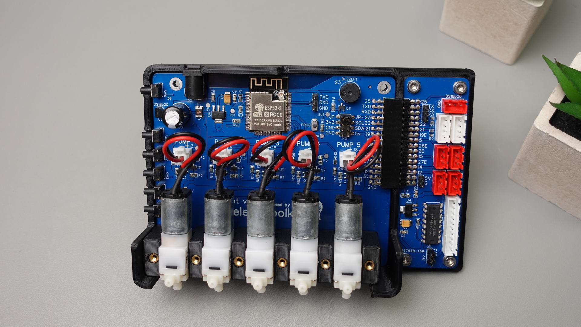
- 5x Micro Pump outputs "5v"
- 5x Soil Moisture sensor inputs "Data-5v-GND" 'Data line pulled down with 1M ohm resistor' ( Data line MAX 3.3v !!!!! )
- Onboard Temperature sensor "DS18B20" https://esphome.io/components/sensor/dallas.html
- Onboard Buzzer "Buzzer port can be free up with jumper" https://esphome.io/components/rtttl.html?highlight=buzzer
- Breakout pins for connecting "i2c OLED Display" https://esphome.io/components/display/ssd1306.html?highlight=display
- 5x Buttons for manual Pumps controll
- 1x Button "Short press" for wake-up Oled "Long press" for general purpose. "2x Binary sensors available for HA"
- All pumps outputs and moisture sensor inputs have fuses
- Pins Which can be used "GPIO 19,5,26,2,15,27,14,12" and "1xi2c GPIO 21,22" "1xUART" "GPIO25 External port for DS18B20 TMP Sensor!!"
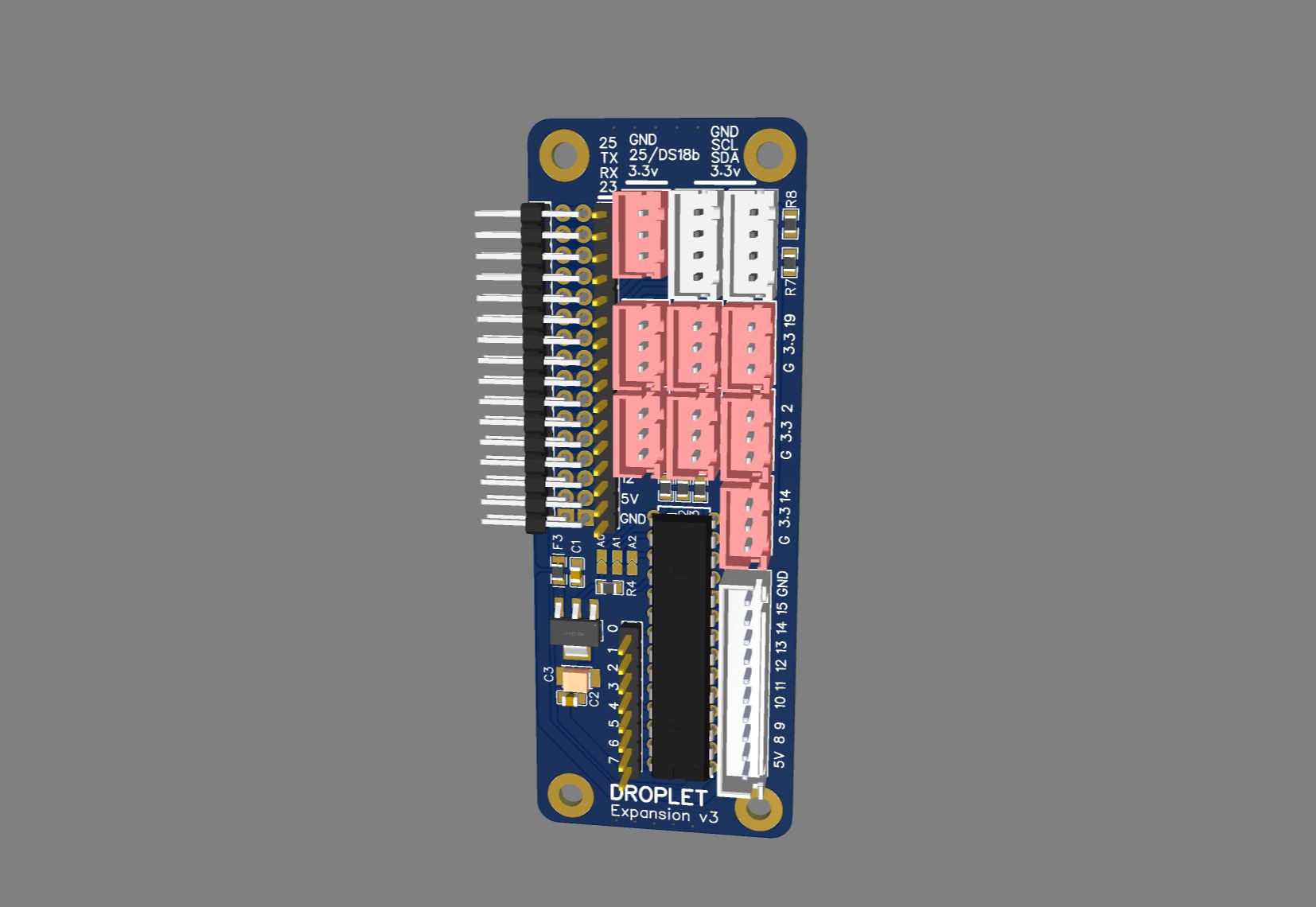
Expansion Board v3
-
1x JST 10pin connector Outputs for 8 Relays "MCP23017" Expander https://esphome.io/components/mcp230xx.html
-
1x 8 Pin Header "MCP23017" Expander https://esphome.io/components/mcp230xx.html
-
2x XH 4pin i2c (V, GPIO 21, GPIO 22 GND)
-
7x XH 3pin GPIO 19,5,26,2,15,27,14
-
1x XH 3pin for "DS18B20 TMP Sensors" (3.3v, GPIO 25, GND)
-
1x 1pin Header GPIO23 connected to buzzer. Buzzer port can be free up, "remove jumper JP"
What sensors Droplet support ?
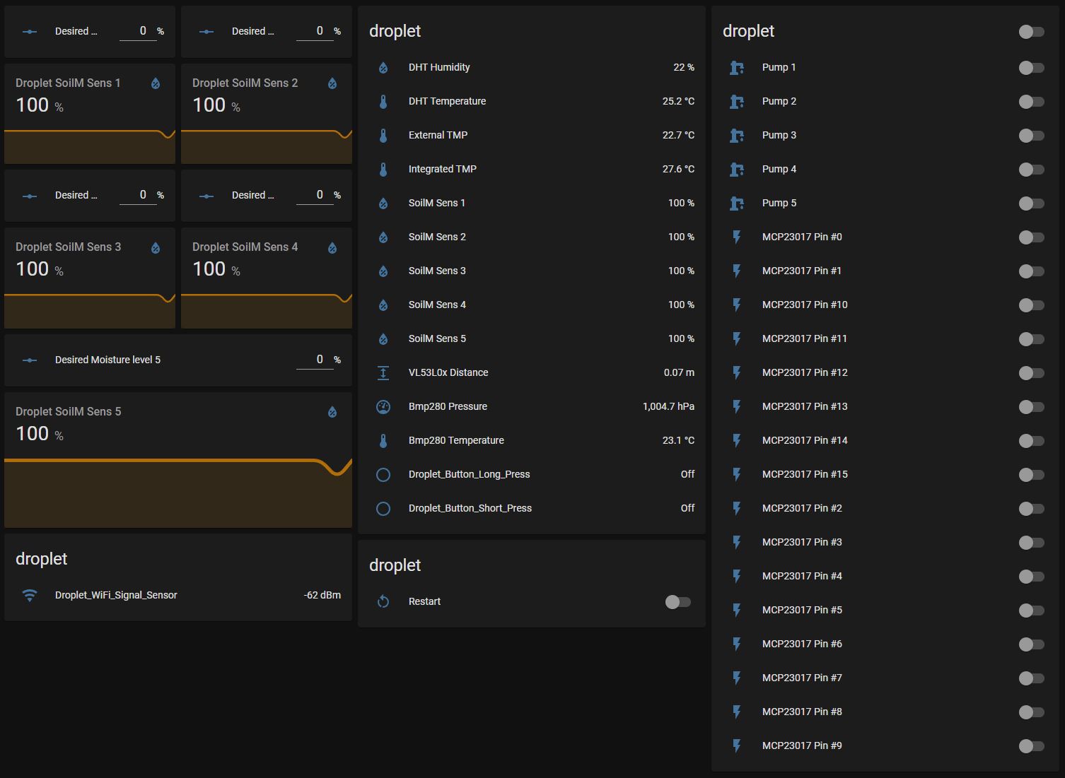
Droplet support "Almost all sensors supported by ESPHome" https://esphome.io/index.html
I connected and tested at the same time.
-
5x Pump
-
5x Moisture Sensor V2,
-
2x "DS18B20" Temperature,
-
1x BMP280 Temperature and Pressure,
-
1x VL53L0x Distance Sensor,
-
1x DHT Temperature and Humidity,
-
8x Relays.
First time setup
WIFI Captive Portal
The captive portal component in ESPHome is a fallback mechanism for when connecting to the configured WiFi fails. After 1 minute of unsuccessful WiFi connection attempts, the ESP will start a WiFi hotspot with the credentials
SSID: "Droplet Fallback Hotspot"
password: "password"
When you connect to the fallback network, the web interface should open automatically (see also login to network notifications). If that does not work, you can also navigate to http://192.168.4.1/ manually in your browser. In this web interface, you can manually override the WiFi settings of the device. Additionally, you can upload a new firmware file to your node without having to use a USB cable for uploads.
<img src="https://esphome.io/_images/captive_portal-ui.png" width="390" height="400" />Reflashing via USB-UART adapter
First, you need to create in the ESPhome new device using the Droplet Config file "don't forget to change it to your needs" then compile it and download the ".bin" file. To upload it to the Droplet, we also need "ESPHome Flasher" software
-
Connect your USB-UART adapter to the Droplet Mainboard "GND, 3.3V, TX, RX"
-
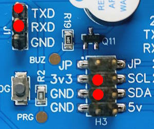
-
Push the "PROG" button on the Droplet Mainboard "Don't release it"
-
Plug the USB-UART adapter to the PC.
-
Upload firmware via ESPHome Flasher.
-
Release the "PROG" button.
Setting the onboard DS18b20 temperature sensor
First of all we need to find out the address of the Onboard temperature sensor. For example with this configuration: "which is already in the default config"
one_wire: #https://esphome.io/components/one_wire
  - platform: gpio
    pin: GPIO25
In the log output (ensure the log level is set to at least debug), you’ll see something like this.
<img src="https://esphome.io/_images/dallas-log.png" width="634" height="321" />With the temperature sensor address identified in the log, we can now enable the Display component by uncomenting this line.
it.printf(5, 15, id(font3) ,"%.1f°C", id(intergratedtmp).state);
It should look like this in the full configuration.
display: # More info https://esphome.io/components/display/ssd1306.html?highlight=1306
- platform: ssd1306_i2c
  id: oled
  model: SSD1306 128x64
  address: 0x3C   # Oled Display Address
  lambda: |-
    it.printf(2, 0, id(font2), TextAlign::TOP_LEFT, "DROPLET");
    it.printf(61, 0, id(font2) ,"%.1f", id(dbm).state);
    it.line(0, 12, 98, 12);
    it.line(98, 0, 98, 64);
    it.printf(102, 0, id(font2) ,"%.1f", id(Soil1).state);
    it.printf(102, 12, id(font2) ,"%.1f", id(Soil2).state);
    it.printf(102, 24, id(font2) ,"%.1f", id(Soil3).state);
    it.printf(102, 36, id(font2) ,"%.1f", id(Soil4).state);
    it.printf(102, 48, id(font2) ,"%.1f", id(Soil5).state);
    it.printf(5, 15, id(font3) ,"%.1f°C", id(intergratedtmp).state);
#   it.printf(5, 30, id(font3) ,"%.1fH", id(dhthumidity).state);
#   it.printf(5, 45, id(font3) ,"%.1fP", id(pressure).state);
Now, uncomment the integrated temperature sensor configuration and add the address.
  - platform: dallas_temp
    address: 0x6e3c......
    name: "${name} Integrated TMP"
    id: "intergratedtmp"
After adding it to the configuration, reinstall the firmware once more.
Part List
!!! Sellers very often change the type of pump to air "Link may not be relevant" !!!
- Power adapter 5v 2-3.5Ah Connector DC-005 2.0 - https://s.click.aliexpress.com/e/_DEsuOdV
- Oled Display - https://s.click.aliexpress.com/e/_DlkmoXv
- Water Pump "Model B JSB1523" 5V - https://s.click.aliexpress.com/e/_DdjCmgL Datashet - https://github.com/PricelessToolkit/Droplet/blob/main/Water_Pump_JSB1523008.pdf
- Silicone tube " inner diameters 3 and 4mm" - https://s.click.aliexpress.com/e/_DBnM9qL
- Heat Set Insert M3 X D4.6 X L4.5 - https://s.click.aliexpress.com/e/_9xbSZC
- Capacitive Soil Moisture Sensor "lottery may be working or defective" - https://s.click.aliexpress.com/e/_9Qz84W
- Cables with connectors for sensors and relays "pin pitch XH 2.54MM" - https://s.click.aliexpress.com/e/_DDpn7iB
- 3D Case "For those who live in France" you can order here - https://www.facebook.com/Upin3d
- Cable for soil moisture sensor https://s.click.aliexpress.com/e/_DDGNx5h

